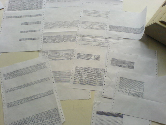
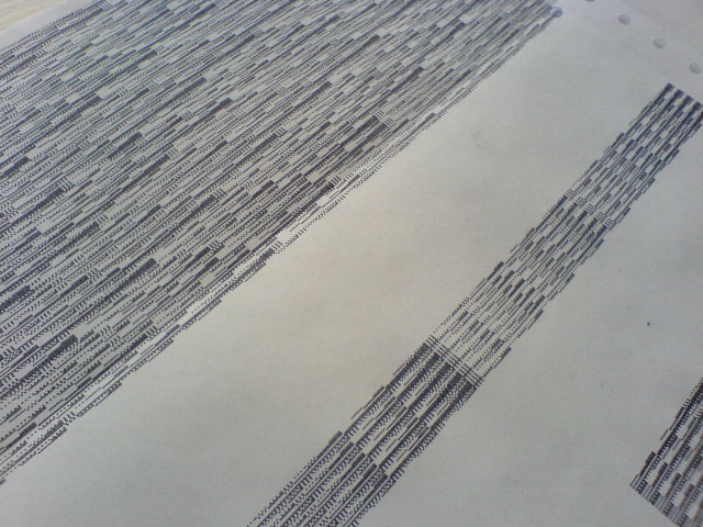
Dot Matrix patterns
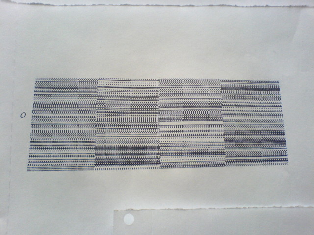
code, hardware - March 25th, 2008 - aymeric - No CommentsIn “hello process”, each iteration, through all the small bits of FORTH code inside the block file image, is visualized as one line of graphics on paper from the dot matrix printer. These graphics are not generated as an image and sent to the printer, but instead are directly using the 8-pin graphics mode of the printer.
In this case, each of the eight bits in a byte of data sent to the printer corresponds to one pin on the printhead. A bit’s value can be either 1 or 0. When the printer receives the data, it interprets a bit with a value of 1 as a command to fire the corresponding pin. Bits that are set to 0 don’t cause pins to fire.
Each block code will end up with its own “byte ID” so it can be visualized and identified on paper in the graphics line. But before getting there, a few tests have been done to try different bit combos and select the generators the most aesthetically pleasing for us :)

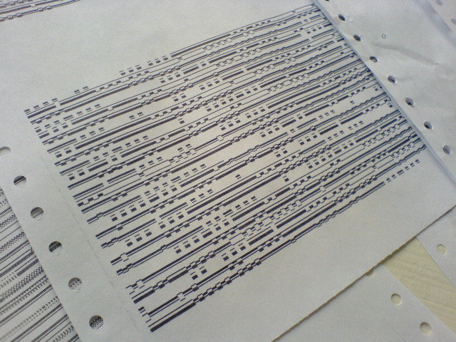

Below, one of the small quick and dirty shell scripts used to quickly test different patterns:
#!/bin/sh

# OKI 320 ML tests

# this test is to generate (crap) random 8 pin mode patterns

#PRNG

function rand {

    echo "obase=8;`expr $RANDOM % 256`" | bc

}

function randpat {

    n=1

    while [ $n -le 256 ]; do

        RND=`rand`

        echo -ne '\'$RND

        n=$((n+1))

    done

}

PATTERN=`randpat`

# noise

# PATTERN2=`head /dev/urandom -c 1024`

echo -e '^[@^[5^[9^[*1\4'$PATTERN'^[@' | lp -o raw